Peter Körner designed a 19-element Yagi for the 88-108 MHz FM broadcast band with a horizontal folded dipole and five reflectors. As the name suggests, this is the third version of this antenna, optimized to 9-11 dBd gain and F/R between 30–38 dB. The distance between first and last element is 5.1 m or 201″. I built this antenna in 2010 for FM DXing in a horizontal polarization and I have been using it for almost 10 years.
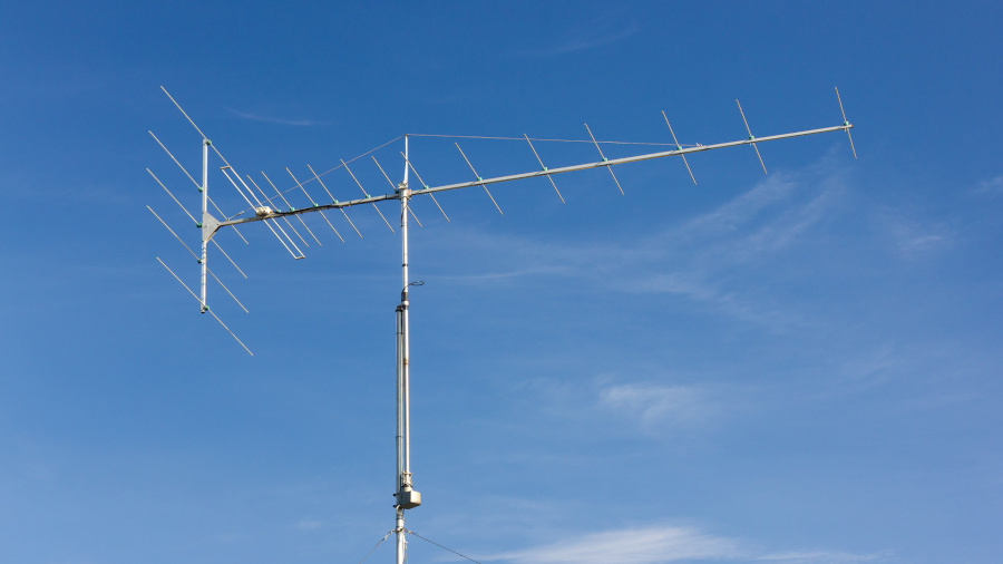
The radiation pattern highly depends on a polarization, as this antenna features a horizontal folded dipole. Its size was designed only for a horizontal polarization, where both arms are parallel to the incoming signal. Brian Beezley, K6STI optimized the F/R ratio further, reaching ≥36 dB over entire bandwidth. For more information check out his website – section Optimized 19.3.
Construction
The antenna file is available in MMANA-GAL format: Korner19_3.maa.
Bill of materials:
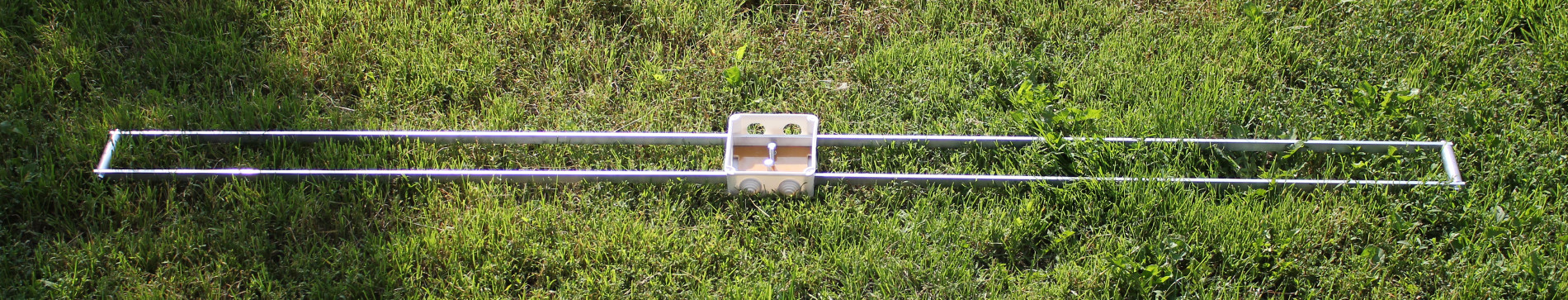
- aluminium square tubes for booms:
- main: 25×25×2 mm (4 meters) + 20×20×2 mm,
- reflectors: 25×25×1.5 mm,
- 1.5 mm duraluminium sheet for main and reflector boom joint,
- 10×1 mm aluminium tubes with insulated mounting brackets,
- many screws, nuts and washers, non-conductive line, u-bolts,
- plastic box, cable gland, F-connectors, 75Ω coaxial cable.
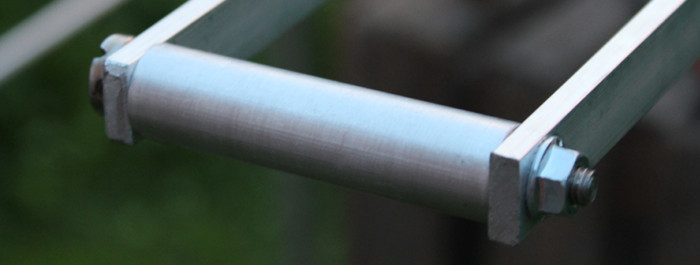
The main and reflector boom joint is made of two pieces of duraluminium sheets. The antenna boom is quite long and it requires additional support. I added non-conductive boom guys which cannot affect the antenna pattern.

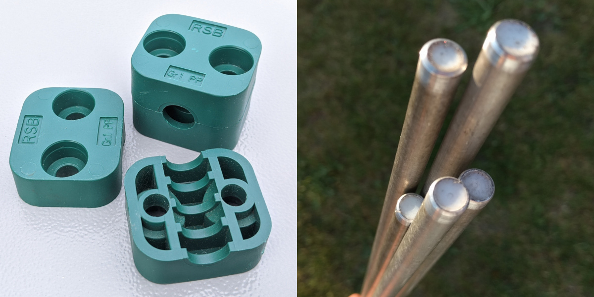
All elements should be installed on insulated mounting brackets. I used RSB RAPR-110 hydraulic tube clamps. Each tube end should be closed. That will prevent acoustic resonance. Furthermore, the water may freeze inside an element and break it in a result during the wintertime. I used some teflon plugs for that.
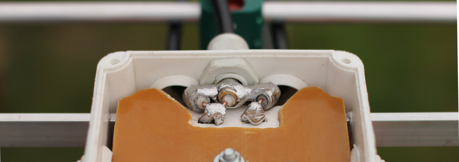
Körner 19.3 uses a dipole made of 15×5 mm aluminium flat bars and ⌀15 mm round tubes between dipole arm ends. Personally I used ⌀16×1.5 mm tubes, because 15 mm were unavailable at my nearby store.
Feedpoint joints use special bi-metallic washers, with one side of copper and one side of aluminum. They prevent corrosion due to dissimilar electrode potential and will provide a long-term reliability. I also used a spray dedicated for PCB coating to protect all joints. Finally, I sealed the plastic box with silicone.
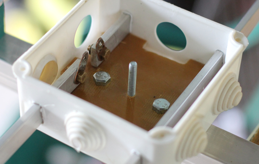
For the 300Ω → 75Ω matching I made a half-wave coaxial balun.
Measurements
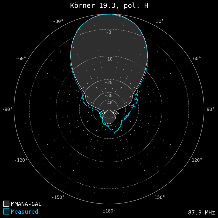
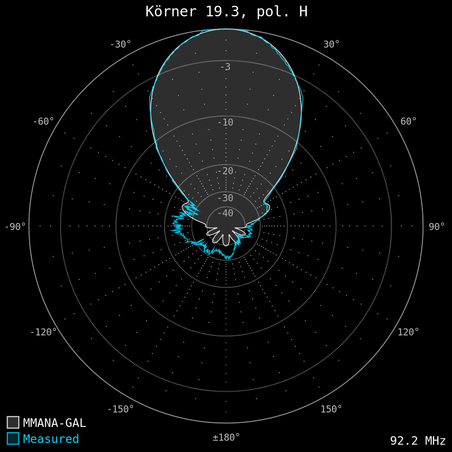
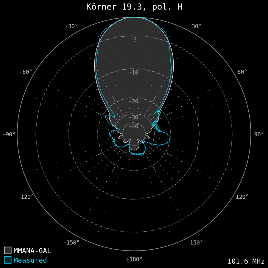
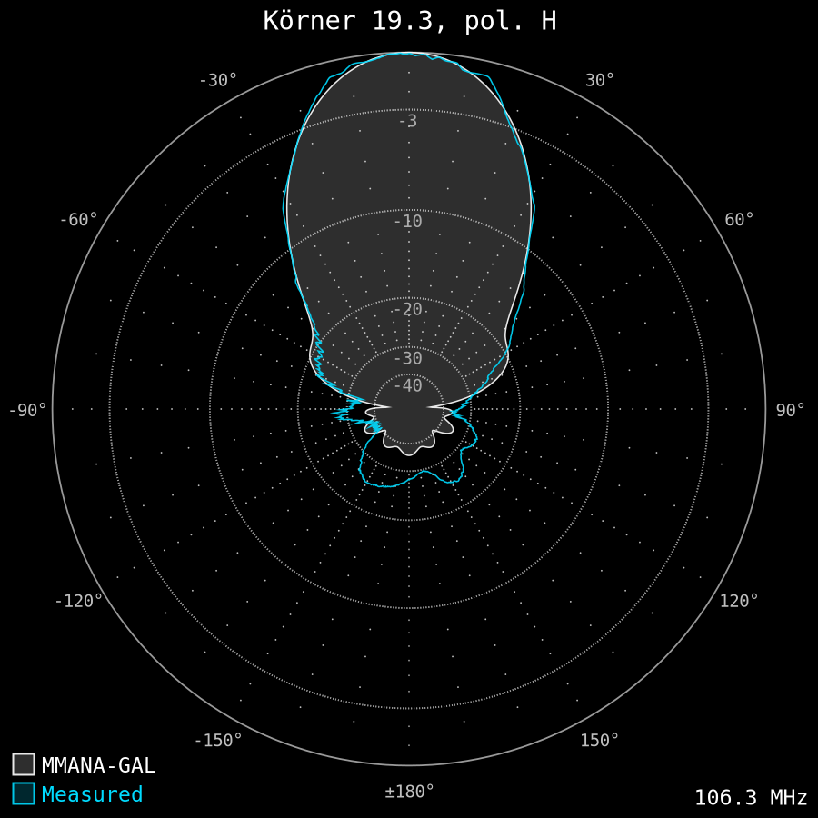
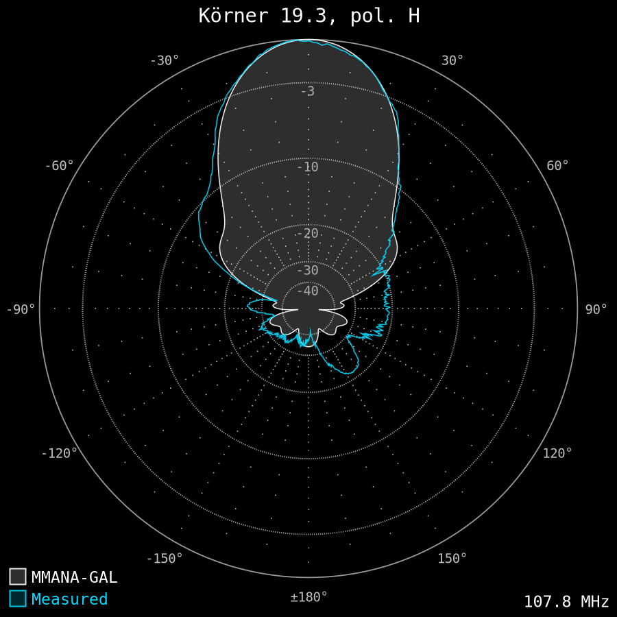
I measured the antenna radiation patterns using a modified Sony XDR-F1HD tuner with a calibrated signal meter and XDR-GTK software. I used some attenuators to keep the signal level below AGC clipping thresholds. I also measured some weaker signals during maintenance of my local transmitter site, that carries 6× 60 kW + 1× 2.5 kW @ 35 km. It should be noted that my rotator (AR-303) is not very linear, especially towards north, where it starts and ends the rotation. The multipath interference is clearly visible in the following plots.
- 87.9 MHz: Radio Maryja Łódź, 10 kW ERP @ 95 km, no attenuator, peak 46 dBf:
- 92.2 MHz: PR1 Sierpc, 60 kW ERP @ 35 km, 30dB attenuator, peak 85 dBf (att. to 55 dBf)
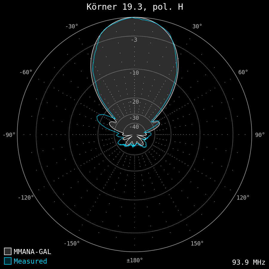
- 93.9 MHz: PR2 Włocławek, 1 kW ERP @ 46 km, no attenuator, peak 52 dBf:
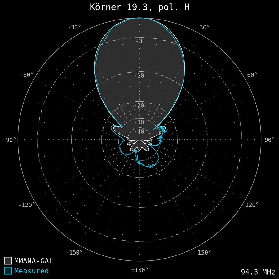
- 94.3 MHz: RMF FM Sierpc, 60 kW ERP @ 35 km, 30dB attenuator, peak 86 dBf (att. to 56 dBf)
- 97.3 MHz: Zet Sierpc, 60 kW ERP @ 35 km, 30dB attenuator, peak 87 dBf (att. to 57 dBf)
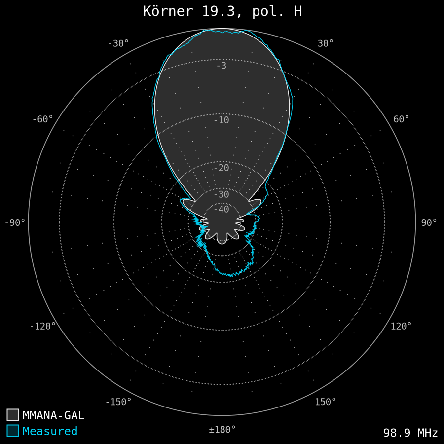
- 98.9 MHz: RMF FM Konin, 30 kW ERP @ 99 km, no attenuator, peak 55 dBf
- 101.6 MHz: PR1 Kutno, 10 kW ERP @ 48 km, 12dB attenuator, peak 70 dBf (att. to 58 dBf)
- 103.3 MHz: PR3 Konin, 30 kW ERP @ 99 km, no attenuator, peak 58 dBf
- 106.3 MHz: Maryja Sierpc, 60 kW ERP @ 35 km, 30dB attenuator, peak 87 dBf (att. to 57 dBf)
- 107.8 MHz: PR1 Łódź, 30 kW ERP @ 95 km, no attenuator, peak 54 dBf


Construction flaws
There are two major flaws that I have encountered.
- Long reflectors are the weakest part of this construction. Frequent vibrations weaken the material near the element brackets – see this video. Use thicker tubes instead (like 10×2 mm) or reinforce the thinner ones. Read more: 2x 9-el Yagi detailed write-up.
- The rectangular folded dipole conductors cannot be sealed with a round cable glands. When I took the antenna down for a maintenance after two years I found some signs of a water corrosion. I filled the remaining space inside the dipole box with a spray foam and sealed it again with silicone. It is (or should be) 100% waterproof now. Another idea is to build the dipole using ⌀12 mm round tube with cable glands, instead of the rectangular flat bars.
The boom guys made of non-conductive material may look a little fragile, but they lasted 10 years without any issues.
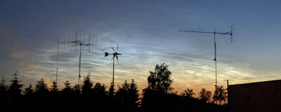
Körner 19.3 & 2× 9-el K6STI with noctilucent clouds in the background (2020-06-16)
FM DXing results
Although the reception is much more propagation and location dependent than just the antenna, it is worth mentioning about real-world FM DXing results. Daily I am able to pick up very distant high-power stations via aircraft scatter propagation mode.
- 89.3 Federalni Radio – Vlašić, Bosnia and Herzegovina (1943 m ASL + 40 m AGL) – 935 km
- 96.5 Radio Beograd 2/3 – Crveni Čot, Serbia (539 m ASL + 60 m AGL) – 828 km
- 99.7 HRT-HR 2 – Psunj, Croatia (985 m ASL + 129 m AGL) – 821 km
At shorter distances, i.e. around 700 km, signals can reach RDS quality via aircraft scatter.
- Arad, Romania (455m ASL + 50m AGL) – 60 kW – 717 km
- Bihor, Romania (1832m ASL + 70m AGL) – 60 kW – 715 km
- Salzburg, Austria (1283m ASL + 46m AGL) – 100 kW – 712 km
The following list contains tropospheric ducting highlights logged using Körner 19.3.
- My distance records – 1682 km Kolari (Finland) and 1643 km Pajala (Sweden) together with over 100 stations from Finland logged during a spectacular propagation in September 2017 (see a short report).
- The United Kingdom, up to 1574 km, incl. Wenvoe, Black Hill, Meldrum, Sutton Coldfield (RDS), Holme Moss (RDS), Pontop Pike (RDS) and more. Two reports are available: June 2019: London, Manchester and Cardiff via tropo in Poland and October 2015: extreme tropo from UK in Poland.
- 100% land-line tropo ducting from central France featuring Bourges-Neuvy @ 1350+ km.
- Norway (now switched off): up to 1200+ km, incl. NRK Petre from Lyngdal @ 1020 km, up to 40 dBf (read full report).
- Croatia @ 1000+ km, received during very strong tropo from the Balkans (read full report).
This antenna is also somewhat usable for OIRT FM DXing (66-74 MHz). This band is empty in Poland, so the F/R ratio is not really important. For the bottom of the band (below 70 MHz) Körner 19.3 should be directed backwards, as the reflectors act as a directors. For the top of band (above 70 MHz) it should be directed right ahead.
- My tropo distance record from Russia in 2019 – 72.17 MHz Radio Rossii from Muyezerskiy @ 1448 km.
- Russian OIRT up to 995 km in 2012 (read full report).
For a full reference see my FM DX Tropo Log – Płock, Poland (Korner’s results are of course the H-pol ones).
Regarding the Sporadic-E propagation, the strongest signals I have ever measured were above 70 dBf.
- 89.4 France Musique – Brest, 158 kW ERP @ 1729 km – 74 dBf.
- 89.0 France Culture – Le Mans, 126 kW ERP @ 1480 km – 72 dBf.
- 89.3 BBC Radio 2 – Holme Moss, 250 kW ERP @ 1443 km – 72 dBf.
- 71.09 Radio Rossii – Stary Oskol, 17 kW (?) @ 1242 km – 69 dBf – out of the band!
Rough free space loss calculation results in the same level as received:
82 – 136 + 9 – 1 = -46 dBm = 74 dBf (ERP [dBm] – FSL [dB] + RX Antenna Gain [dBd] – Cable Losses [dB]).
Summary
Körner 19.3 is definitely one of the best – if not the best – 88-108 MHz antenna ever designed. Personally, I was not able to take full advantage of its superb F/R ratio due to some multipath interference. There are metal roofs, high voltage power lines and the worst – a nearby oil refinery with several chimneys and many metal constructions.
The following video recorded in August 2010 presents the Körner 19.3 at an initial height of 7.5 m. The mast was extended to 10 m two years later. In the year 2014 there was another attempt to extend it to 12 meters, but the mast got bent during lifting.
Within 10 years of DXing several cheap rotators were damaged by wind and repaired several times. The gears were being damaged every one or two years. Some of them were replaced, what resulted in faster rotation speed, as it was not possible to find the same original ones. Not a big deal anyway, as I was not using the original controller.
I pulled the antenna down in June 2020. First of all, I was not able to repair the rotators endlessly. Secondly, I needed more space for my Wi-Fi DXing setup rebuild, which was damaged in May 2020.
Last update: July 2020