
Wi-Fi DXing is an activity of searching for distant Wi-Fi wireless networks during enhanced weather conditions which allow radio waves to travel farther than typically.
Wi-Fi networks usually operate in 2.4 GHz or 5 GHz radio band. Such high frequencies are characterized by high free-space losses and strong attenuation due to any obstructions. The range is limited to several hundred meters or so using typical equipment. This can be greatly extended with external antennas, but the line of sight is mandatory at microwave frequencies.
Under some favorable circumstances, the radio signals can be received much farther than expected. This phenomenon is the same as mirage, where rays of light are bent, effectively extending the optical horizon. Similarly, the sound waves can also be refracted and returned towards the ground under some conditions. Finally, this also applies to radio waves.
The 5 GHz band is very crowded nowadays, as it is widely used by the ISPs (internet service providers) with outdoor equipment installed on tall buildings. With an external antenna installed at a reasonable height above ground, the signal can travel several dozens of kilometers. Very good propagation conditions can extend the range to hundreds of kilometers beyond the horizon.
Tropospheric propagation
The propagation of radio waves strongly depends on the conditions within the troposphere, which is the lowest layer of Earth’s atmosphere. Usually, the temperature decreases with height above the Earth. When there’s an inversion, i.e. the opposite of what is normally the case, radio signals can extend their range beyond the horizon. In short, an enhancement in propagation is commonly called tropo.
General information:
- Inversion layer can bend the radio waves back to the Earth’s surface, instead of going into the space.
- Under special conditions, radio waves may get trapped into inversion layer, travelling far away in a form of duct.
- Tropospheric propagation favors fairly flat terrain.
- The best results are typically obtained along the lines of an equal pressure (isobars).
- The steeper inversion gradient, the better propagation strength.
The most common mode of tropospheric propagation on microwave bands is caused by radiation inversion.
- Develops at night after a warm and sunny day, when the ground cools off and radiates the heat to the cloudless sky.
- Follows the topography of the land. Initially increases levels of nearby signals beyond the horizon, typically below 100 km.
- The distances increase throughout night. Sun heats up the Earth’s surface in the morning, but the inversion layer is still present. This can result in an elevated duct for a short period of time.
- Stronger wind gusts mix up the air and weaken or even destroy the inversion layer.
- It can be very effective at microwave frequencies and may not fit lower frequencies, like VHF.
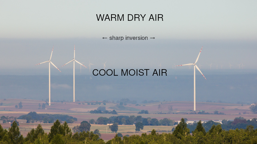
Another type of propagation, based on the advection inversion, occurs where warm dry air passes over a cool moist surface (or vice versa). It has similar effect as radiation inversion, but the directions and distances change as the air masses move further. It happens often after heavy rain (storm), when the ground is cooled down, the weather improves (clouds are gone, wind is weak) and warm dry air is moving in. This mode can be also very effective for microwave bands.
Subsidence inversion usually happens during periods of stable anticyclonic weather and affects radio frequencies in VHF, UHF and microwave bands. Air in a high-pressure system warms up and dries as it descends. Cool and moist air can get trapped underneath such layer, forming an inversion. In contrast to other modes, it can last all day and result in very long distances. This mode does not seem to be very effective for Wi-Fi DXing.
There are also other modes of propagation, like tropospheric scatter, which is present all the time. Temperature and humidity variations can bring the signal beyond normal line-of-sight range. This mode is not usable for Wi-Fi networks though, as it requires very high power (measured in kilowatts) and exceptionally big antennas (several meters long or more).
Upper layers of the atmosphere above troposphere do not affect the propagation of microwave frequencies.
For more reference see:
- Wikipedia:
- William R. Hepburn, Tropospheric DX Modes
- Tropospheric propagation forecasts:
IEEE 802.11 standards
Wi-Fi devices configured in access point mode transmit beacon frames which contain information about the network, typically around 10 times per second. The lowest available modulation depends on the used standard.
- 802.11b (2.4 GHz only) uses DBPSK modulation on 22 MHz DSSS channel.
- 802.11a/g (2.4 or 5 GHz) uses BPSK modulation with FEC 1/2 on 20 MHz OFDM channel (effectively ~16 MHz for 52 subcarriers).
The more recent Wi-Fi standards, like 802.11n or 802.11ac introduced additional features like multiple spectral streams or high order modulation (256-QAM), but because of backward compatibility, the beacon frames are still being broadcast at the lowest modulation rate in a single stream.
It is also possible to perform active scanning by sending a probe request and receiving a probe response without waiting for a beacon frame on a given channel.
![]()
The power of Wi-Fi equipment do not exceed several hundred milliwatts and the strongest devices reach up to around 30 dBm (1 W). Wide channels significantly limit the receiver sensitivity to few microvolts. The real-world sensitivity is at around -94 dBm for 802.11a/g (e.g. Ubiquiti XR5) and a few dB better for 802.11b (e.g. Ubiquiti XR2 at -97 dBm).
Location
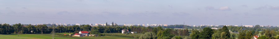
Location is very important, as tropospheric propagation favors flat terrain between antennas. Having the antenna at a higher elevation above average terrain is an advantage. The microwave frequencies are very strongly attenuated by any obstacles. The higher frequency, the higher attenuation. Therefore, antenna must be installed at a height over all nearby buildings, trees and other obstacles. The elevation angle at horizon should be clear at 0° or better for best results.
Antenna & rotator
Antenna is the most important matter. Generally, the higher gain, the better results can be obtained, but that comes with a narrow antenna beam. It is easy to achieve high gain figure on microwave bands, because of a relatively short wavelength. There are many designs around. The largest dual-polarized parabolic dishes available on the market are manufactured by Ubiquiti with diameters up to 1-1.5 m (RocketDish, MonsterDish).
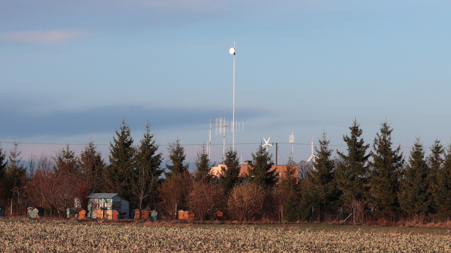
RocketDish RD-5G31-AC antenna at the top of 18 meter mast (click for more info)
Antenna rotator is another must-have thing, with precise positioning (1° recommended). The antenna mast should be well-verticalized in order to keep the same elevation angle in all directions. For instance, ⌀ 105 cm dish rated at 34 dBi peak gain on 5 GHz has a beamwidth of 3° for -3 dB (half-power).
Wi-Fi DX targets & identification
The network location identification is possible using several online databases like Wigle.net or Google Geolocation API. It is also possible to identify the networks during an activity called wardriving (searching for Wi-Fi wireless networks).
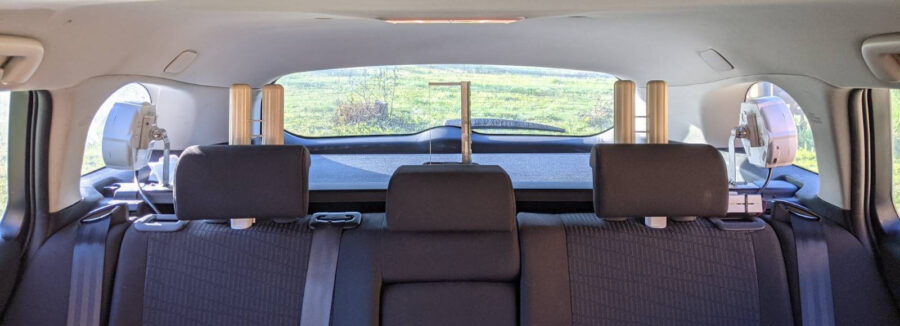
Wi-Fi network scanning in a car, i.e. wardriving (click for more info)
Wi-Fi DX records
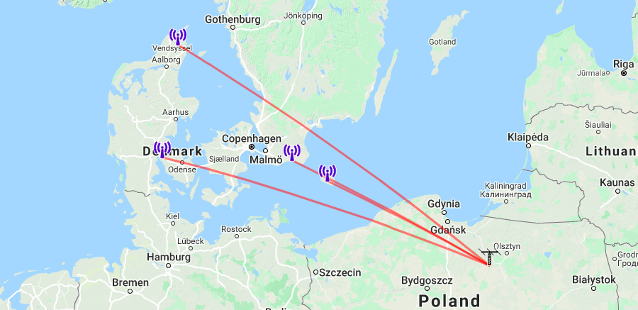
The best mixed path (land + water): Denmark (Sindal) → Poland (Dylewska Góra) @ 745 km (2020-08-12)
- BSSID: 78:8A:20:E4:E9:14
- SSID: wified_16-3 (9870_Tislumvej_480_AP16-3)
- TX: unknown (Ubiquiti Airmax AC PTMP)
- RX: Ultradish TP-550 (27 dBi) + Mikrotik R11e-5HnD
- Frequency: 5240 MHz
- RSSI: -90 dBm
- Geolocation: based on network name – 745 km
Report: 5 GHz Wi-Fi DX record – Denmark logged in Poland @ 745 km
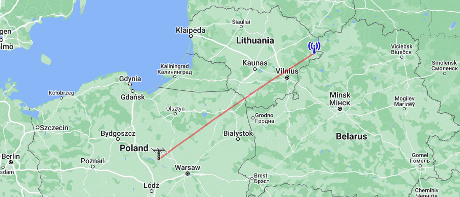
The best land-line path: Lithuania (Bernotai) → Poland (Płock) @ 531 km (2022-08-27)
- BSSID: 78:8A:20:A4:00:8B
- SSID: mezon_airmax_bernotai (IGN_BSUU_bernotai_02_vb)
- TX: unknown (Ubiquiti Airmax AC PTMP)
- RX: RocketDish 5G34 (34 dBi) + Mikrotik Metal 5SHPn
- Frequency: 5745 MHz
- RSSI: -90 dBm
- Geolocation: based on network name – 531 km
Reports: The Best of Wi-Fi DX
Home devices
Almost all distant Wi-Fi networks are coming from external outdoor equipment, i.e. 99% of logged networks. One can find some wireless ISPs around that install their devices on highly elevated locations like chimneys, blocks of flats or dedicated lattice masts. However, it is also possible to receive signals from home routers at surprisingly long distances during very strong tropospheric ducting propagation.
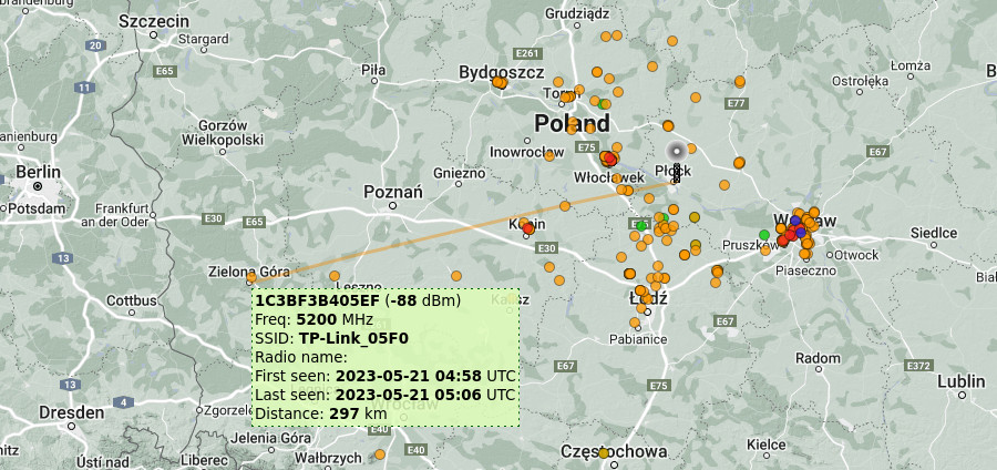
Current record (2023-05-21):
- BSSID: 1C:3B:F3:B4:05:EF
- SSID: TP-Link_05F0
- TX: TP-Link Archer A6 v2 (WPS probe response identification)
- RX: RocketDish 5G34 (34 dBi) V-pol + Mikrotik Metal 5SHPn
- Frequency: 5200 MHz
- RSSI: -88 dBm
- Geolocation: Google Geolocation & personally confirmed
- Distance: 297 km (100% land-line path)
Previous record (2022-08-26):
- BSSID: 48:D2:4F:14:9B:18
- SSID: FunBox2-9B17
- TX: Sagemcom CS50001 (tentative)
- RX: RocketDish 5G34 (34 dBi) + Mikrotik Metal 5SHPn
- Frequency: 5500 MHz
- RSSI: -85 dBm
- Geolocation: Google Geolocation & personally confirmed
- Distance: 281 km (100% land-line path)
See more: Map of identified indoor networks received near Płock, Poland
Read more
- Story of Wi-Fi DXing (background and equipment)
- Ubiquiti RocketDIsh 5G34 (105 cm dish antenna)
- 5 GHz Wardriving System (network identification)
- The Best of Wi-Fi DX (records)
- Tropospheric propagation reports:
- October 2017: 5 GHz Wi-Fi DX 360+ km record via tropospheric ducting (link record)
- New Year 2020: Excellent inversion over Poland (signal strength & network count record)
- 5 GHz Wi-Fi DX record – Denmark logged in Poland @ 745 km (the best distance record)
Congratulations Konrad, for the development of XDR-GTK and subsequent updates.
I am trying the v1.2beta with my awesome TEF-6686!
Just a quick question… is planned in your future a useful 88-108 MHz bandscan with save to file of a log/report with decoded RDS data?
Many thanks,
Paolo Romani, iz1mll