Brian Beezley, K6STI designed a small 5-element Yagi for the 88-108 MHz VHF-FM band with a bent driven element which greatly improves the radiation pattern in a simple single reflector design. His antenna optimizer managed to achieve 5-7 dBd gain and F/R 20-22 dB. I built two of them in the 2011 and installed in the 2012 for receiving vertically polarized signals. They were replaced in the 2013 with 2× 9-el K6STI Yagi setup. In 2020 I installed them back again, but this time in a horizontal stack.
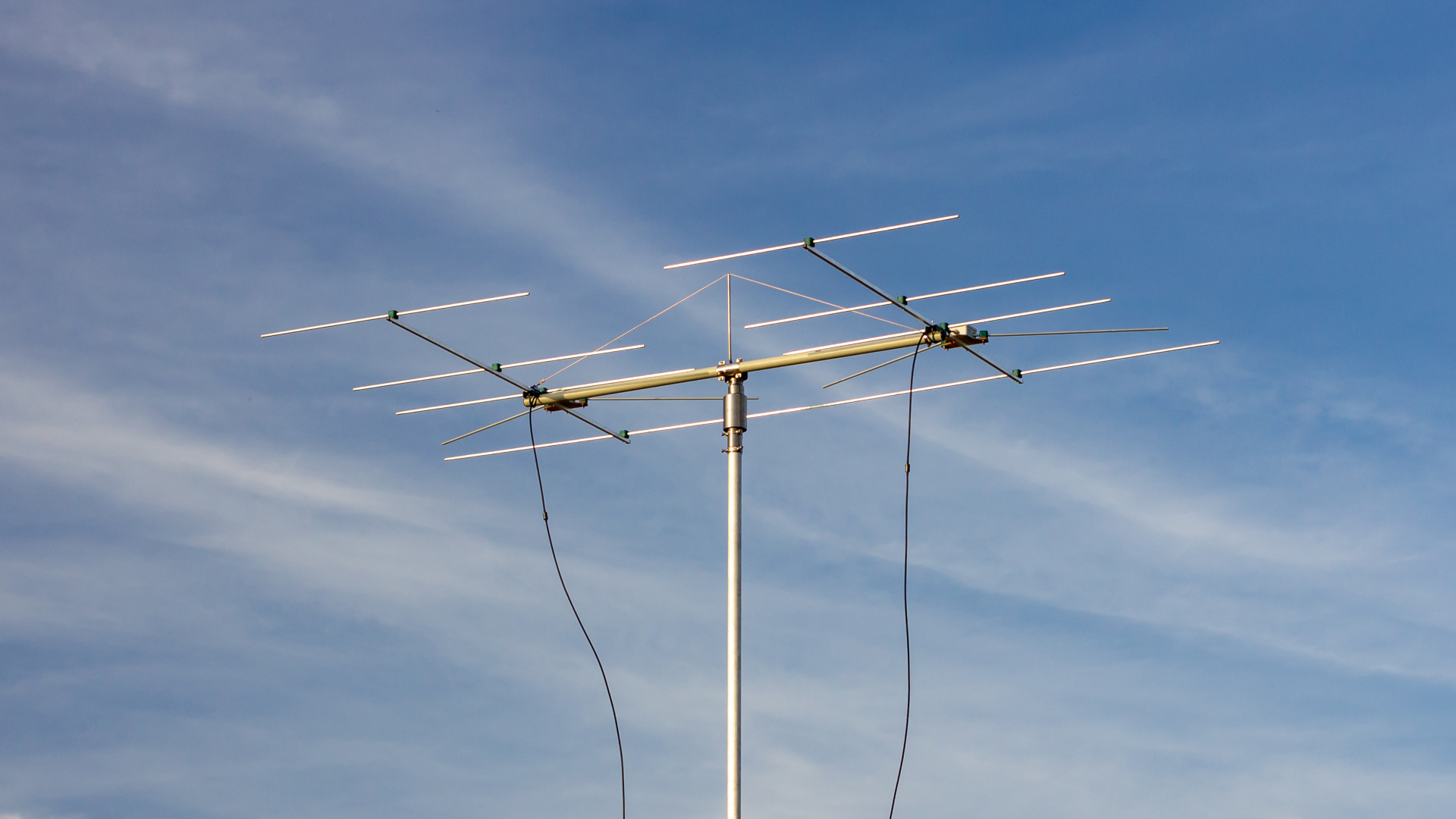
This antenna features a bent driven element optimized for horizontal polarization. The first plot below compares both patterns for vertical and horizontal installation of a single antenna. The second plot compares it with a stack (1.7 m distance).

Construction
The antenna files are available on Brian’s website: http://ham-radio.com/k6sti/five.htm#files
Bill of materials:
- Aluminium square booms: 15×15×1.5 mm.
- 40×5.5 mm non-conductive round PP cross-boom with non-conductive guys.
- 10×1 mm aluminium tubes with insulated mounting brackets.
- 8 mm fiberglass rod for reflectors reinforcement.
- Screws, nuts and washers (stainless).
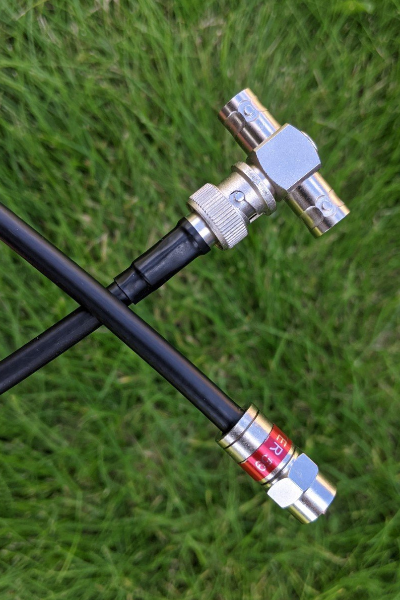
- Plastic boxes, cable glands, ferrite chokes, BNC connectors, 75Ω coaxial cable.
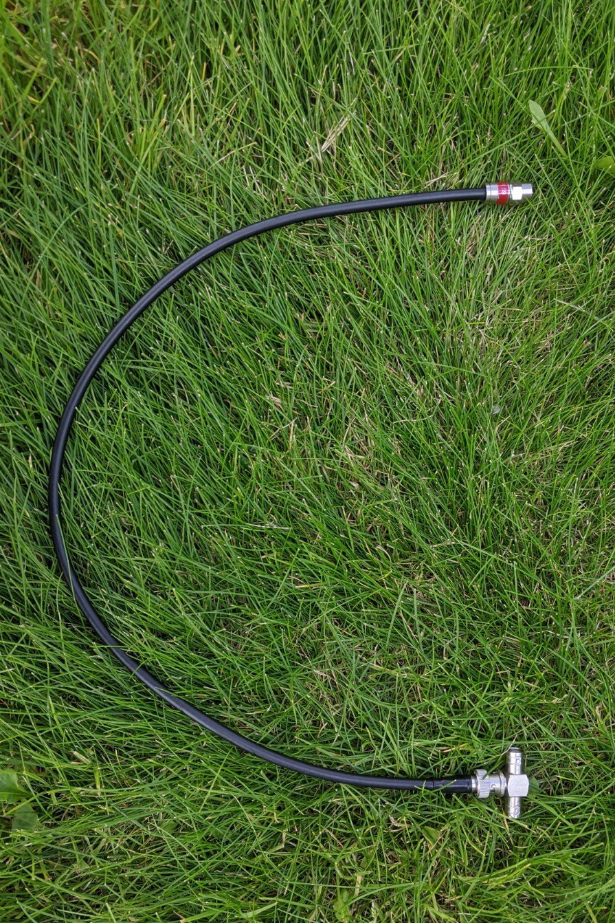
- BNC T-adapter and CNT240 50Ω coaxial cable for 37.5Ω -> 75Ω matching.
All elements should be placed on insulated mounting brackets. I used RSB RAPR-110 hydraulic tube clamps. Each tube end should be closed. I filled all tubes with spray foam.
The most difficult part of this construction is the driven element, which has to be mounted at a specific angle. I used Marlanvil 003.CS (IP65) box for the feedpoint protection. Bimetallic washer with copper and aluminum surface is recommended for the inner conductor joint. The coaxial cable, which I used, has an aluminium braid, so it can be joined directly to the driven element.
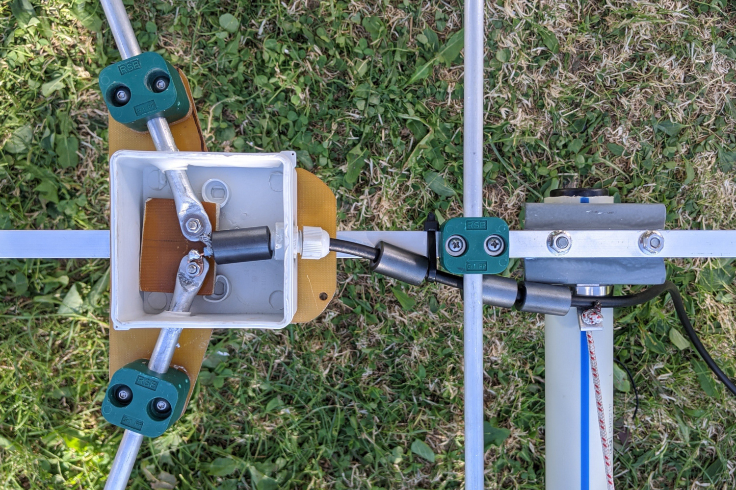
Although dipole impedance is the same as the coaxial cable (75 Ω), it requires coiled-coax balun or ferrite chokes to attenuate any unwanted shield current. I used five RRH-175-83-285 ferrites, each rated 242Ω at 100 MHz, for each antenna. The first one is installed directly at the feedpoint. Three more are placed outside the plastic box, near the feedpoint. And the last one is installed 76 cm away from the feedpoint.
I used a non-conductive round PP tube for a cross-boom, but it is very unstable on its own. The non-conductive guys helped a lot, but that was still not enough. Finally, I added a fiberglass rod for reflectors reinforcement, which greatly stabilized this construction.

I combined both antennas with a T BNC adapter. The cable length between each antenna and the T adapter must be the same. Combining two 75Ω signals results in a 37.5 Ω output. Matching 37.5 Ω back to 75 Ω is done with a 1/4λ 50 Ω coax. I used Andrew CNT240 cable with 83% velocity ratio with a length of 300/98/4*0.83 = 63.5 cm.
Measurements
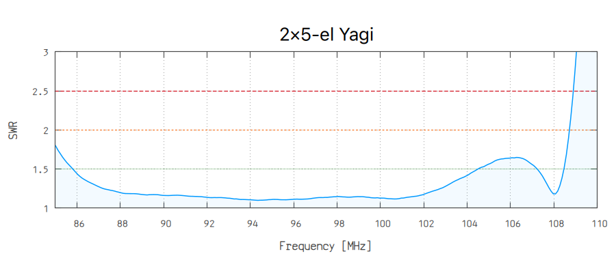
I measured the return loss using NanoVNA V2 Plus4 calibrated directly at the twelfth-wave transformer (50 to 75Ω).
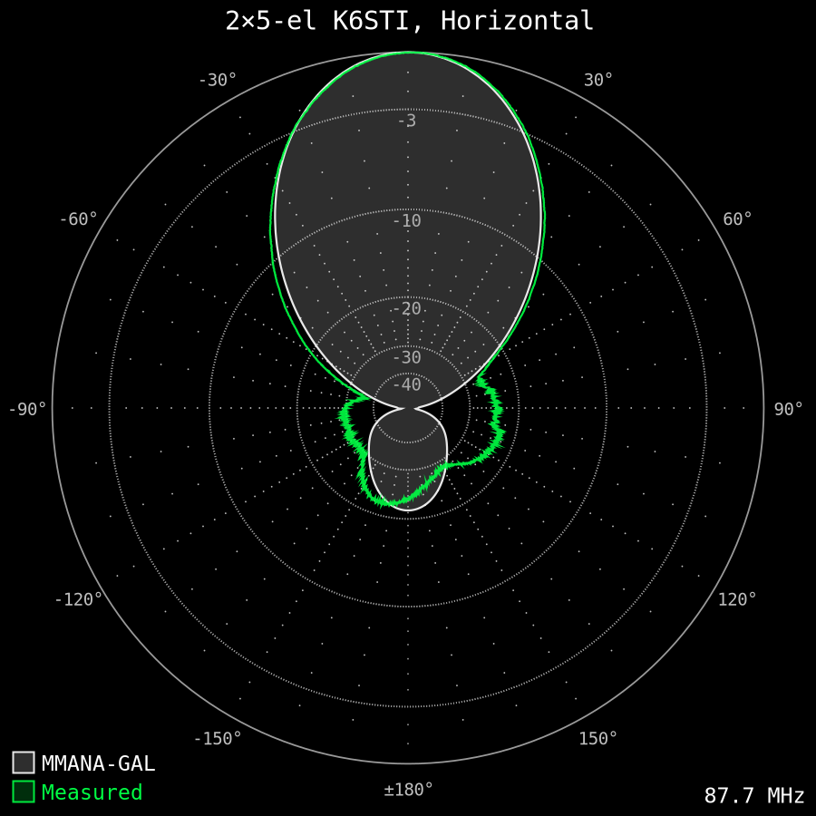
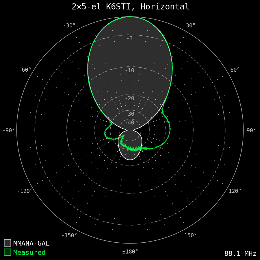
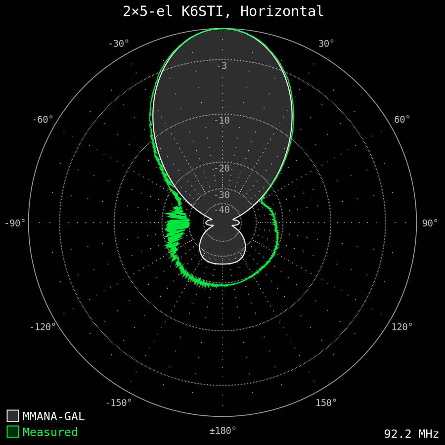
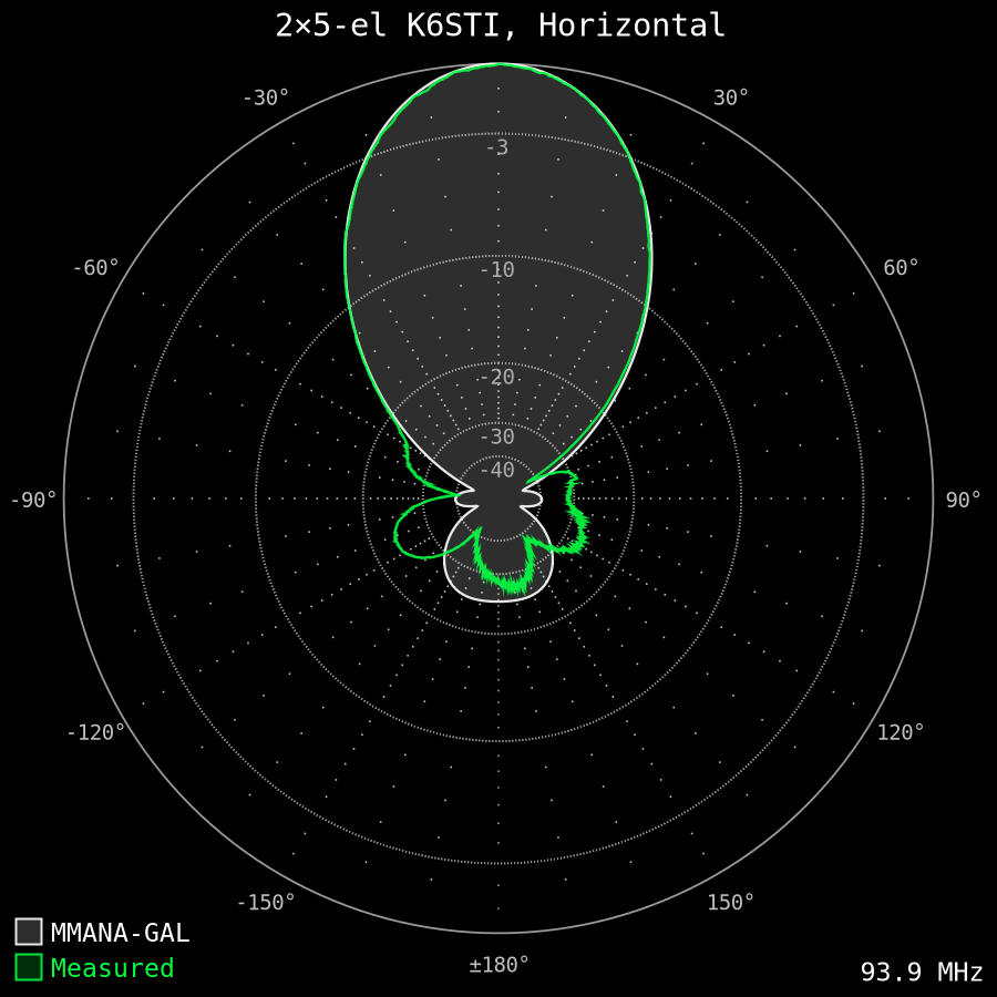
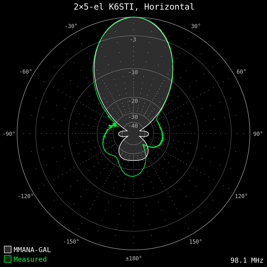
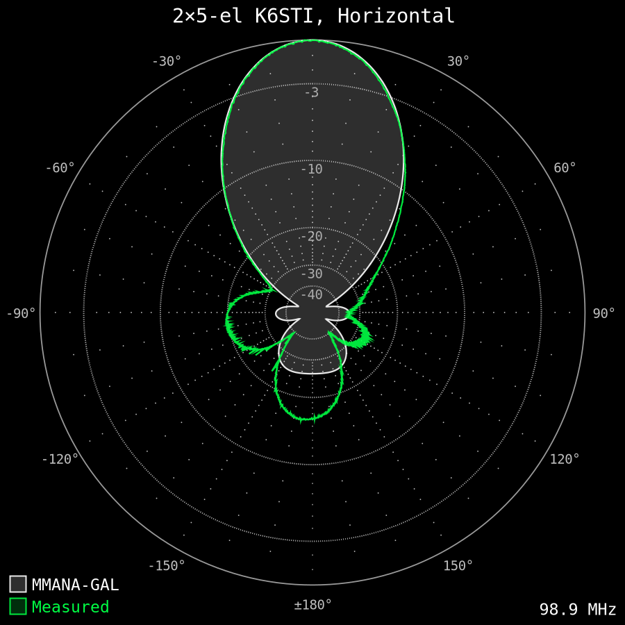
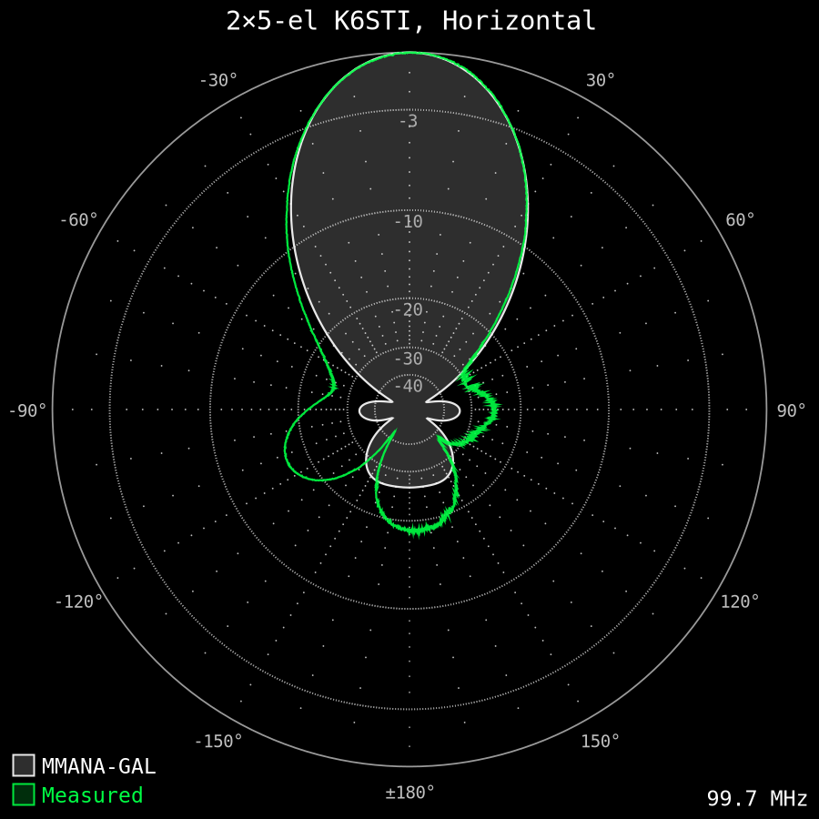
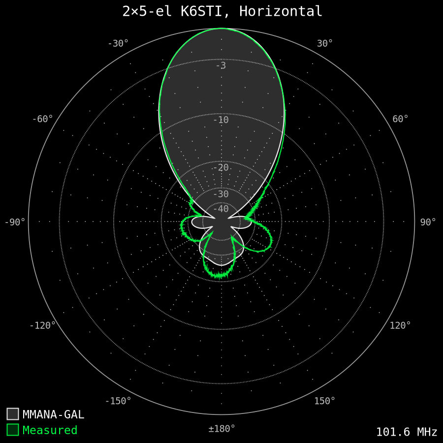
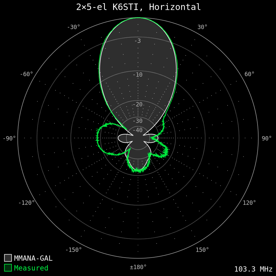
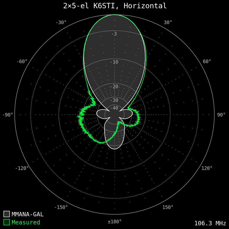
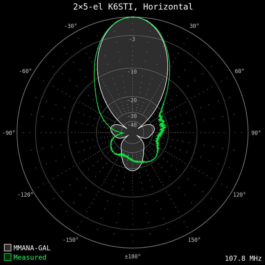
I measured the antenna radiation patterns using a Airspy HF+ tuner with GNU Radio and XDR-GTK software. The multipath interference is visible as noise in the following plots.
- 87.7 MHz: PR 1 Konin, 60 kW ERP @ 95 km
- 88.1 MHz: Płock FM, 1 kW ERP @ 10 km
- 92.2 MHz: PR1 Sierpc, 60 kW ERP @ 35 km
- 93.9 MHz: PR2 Włocławek, 1 kW ERP @ 46 km
- 94.3 MHz: RMF FM Sierpc, 60 kW ERP @ 35 km
- 96.1 MHz: PR3 Sierpc, 60 kW ERP @ 35 km
- 97.3 MHz: Zet Sierpc, 60 kW ERP @ 35 km
- 98.1 MHz: PR2 Sierpc, 2.5 kW ERP @ 35 km
- 98.9 MHz: RMF FM Konin, 30 kW ERP @ 99 km
- 99.7 MHz: PR24 Płock, 0.2 kW ERP @ 10 km
- 101.6 MHz: PR1 Kutno, 10 kW ERP @ 48 km
- 101.9 MHz: RDC Sierpc, 60 kW ERP @ 48 km
- 103.3 MHz: PR3 Konin, 30 kW ERP @ 99 km
- 106.3 MHz: Maryja Sierpc, 60 kW ERP @ 35 km
- 107.1 MHz: Zet Konin, 60 kW ERP @ 95 km
- 107.8 MHz: PR1 Łódź, 30 kW ERP @ 95 km


Summary
Taking into account quite small antenna size and only a single reflector design, the performance is very good.