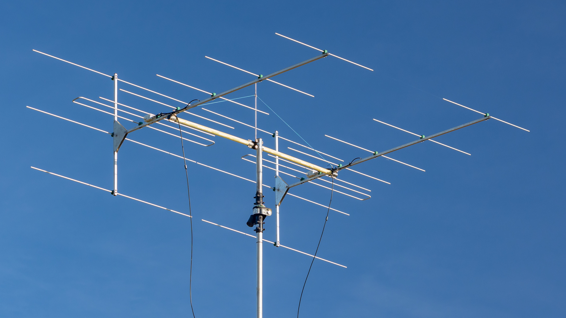
Brian Beezley, K6STI designed a 9-element Yagi for the 88-108 MHz VHF-FM band with a horizontal folded dipole and three reflectors. His antenna optimizer managed to achieve 7-8 dBd gain and F/R up to 30dB over entire bandwidth. The distance between first and last element is 100″ or 254 cm. Currently, a shortened version is well known as Körner 9.2.
I built two of them in 2013 for receiving vertically polarized signals and they were replaced with 2×8-el Yagi in 2021.
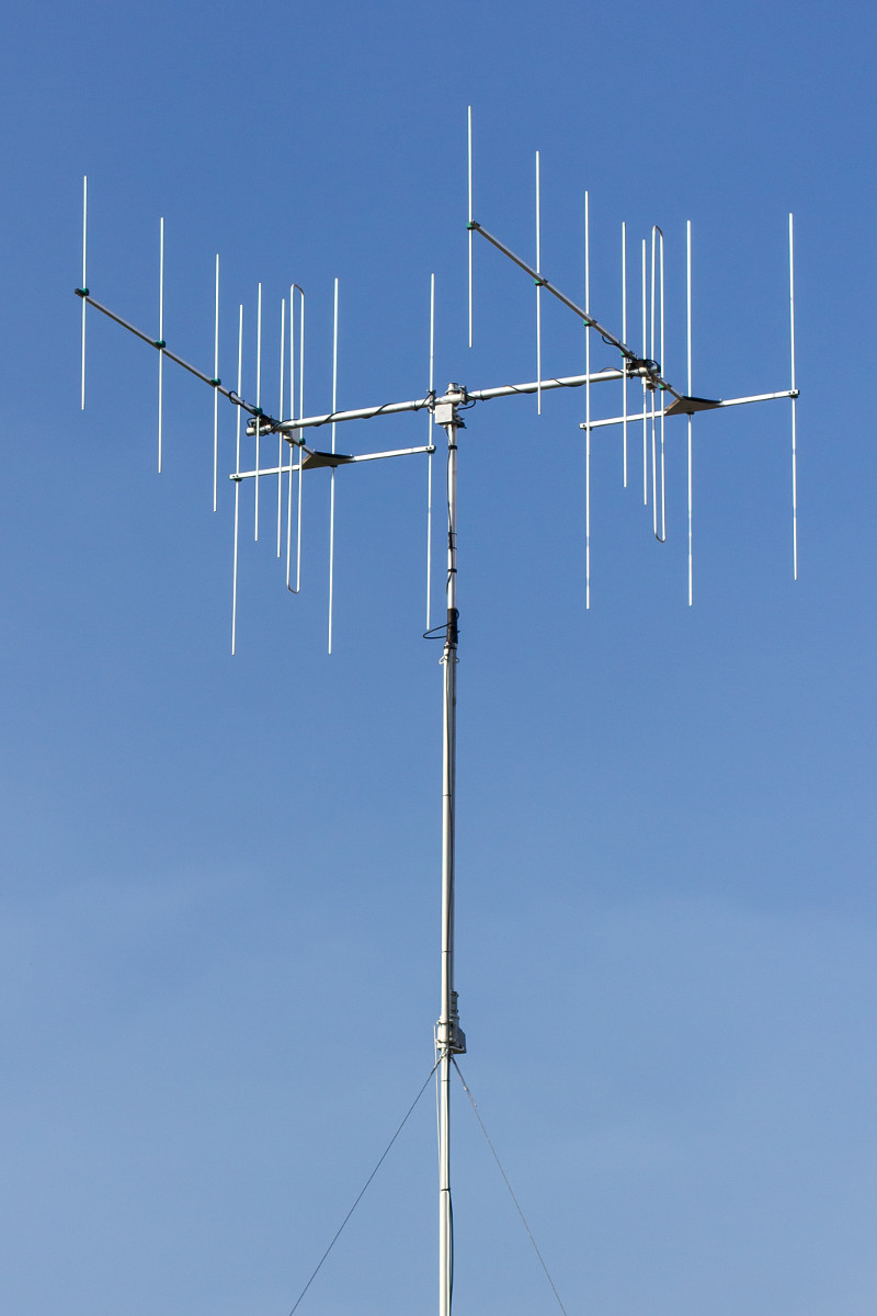
I installed them again in 2023, but in horizontal polarization.
A single dipole antenna has a different pattern depending on its polarization. In vertical it is omni-directional and in horizontal it has two lobes with deep nulls at ±90°. Similarly, Yagi antenna has much better directivity in a horizontal polarization. This antenna additionally uses a horizontal folded dipole with its size optimized for horizontal polarization. Because of that, the 30 dB F/R figure applies only to that polarization. The following plots compare both patterns for vertical and horizontal installation of a single antenna.
The 30 dB F/B (not F/R) ratio is preserved in vertical, as both arms of the horizontal folded dipole are inline with the vertically polarized signals coming from the behind.
Dimensions
The antenna file is available in MMANA-GAL format: 9el_K6STI.maa.
100" 9-Element Yagi
Free Space Symmetric
88 92 98 100 105 107 108 MHz
11 6063-T832 wires, inches
z = 20.8558			; reflector height
r0 = 38.59764			; reflector half-lengths
r1 = 36.38081
de = 31.14668			; driven element half-length
d1 = 26.07912			; director half-lengths
d2 = 25.77762
d3 = 25.34543
d4 = 24.59307
d5 = 21.915
de1 = 13.70858			; driven element positions
de2 = 18.02412
d1p = 22.33073			; director positions
d2p = 31.9882
d3p = 49.21343
d4p = 71.10764
d5p = 100
1      0  0  z      0  r1  z    .375
1      0  0  0      0  r0  0    .375
1      0  0 -z      0  r1 -z    .375
1    de1  0  0    de1  de  0    .375
1    de2  0  0    de2  de  0    .375
1    de1 de  0    de2  de  0    .375
1    d1p  0  0    d1p  d1  0    .375
1    d2p  0  0    d2p  d2  0    .375
1    d3p  0  0    d3p  d3  0    .375
1    d4p  0  0    d4p  d4  0    .375
1    d5p  0  0    d5p  d5  0    .375
1 source
Wire 5, end1
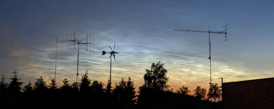
Körner 19.3 & 2× 9-el K6STI with noctilucent clouds in the background (2020-06-16)
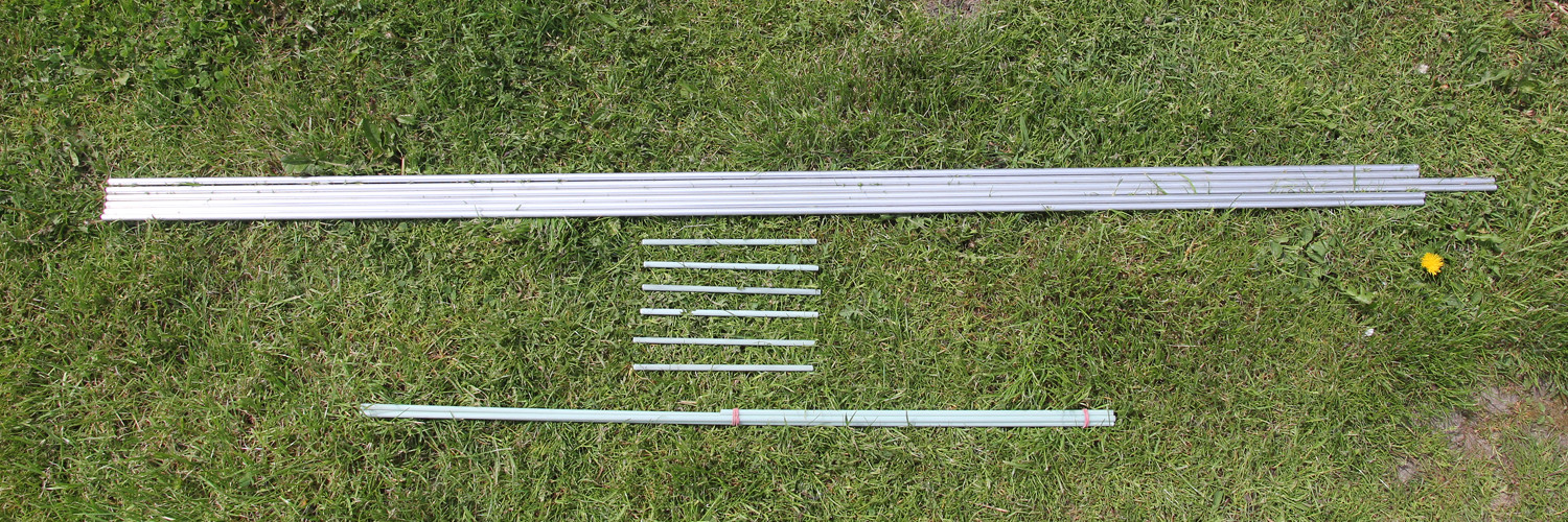
Construction

Bill of materials:
- aluminium square tubes for booms:
- main: 20×20×2 mm,
- reflectors: 20×20×1.5 mm,
- 1.5 mm duraluminium sheet for main and reflector boom joint,
- 10×1 mm aluminium tubes with insulated mounting brackets,
- 40×2 mm aluminium tube (horizontal mast) and some u-bolts,
- many screws, nuts and washers (stainless),
- plastic boxes, cable glands, ferrite chokes, F-connectors, 75Ω coaxial cable,
- T adapter and 50Ω coaxial for 37.5Ω -> 75Ω matching.
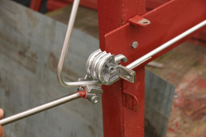
The main and reflector boom joint is made of two pieces of duraluminium sheets.
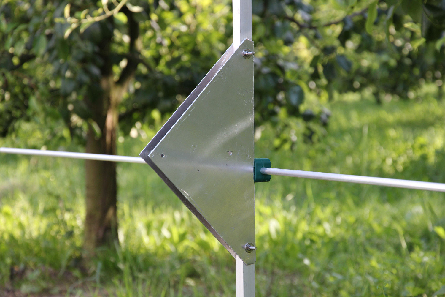
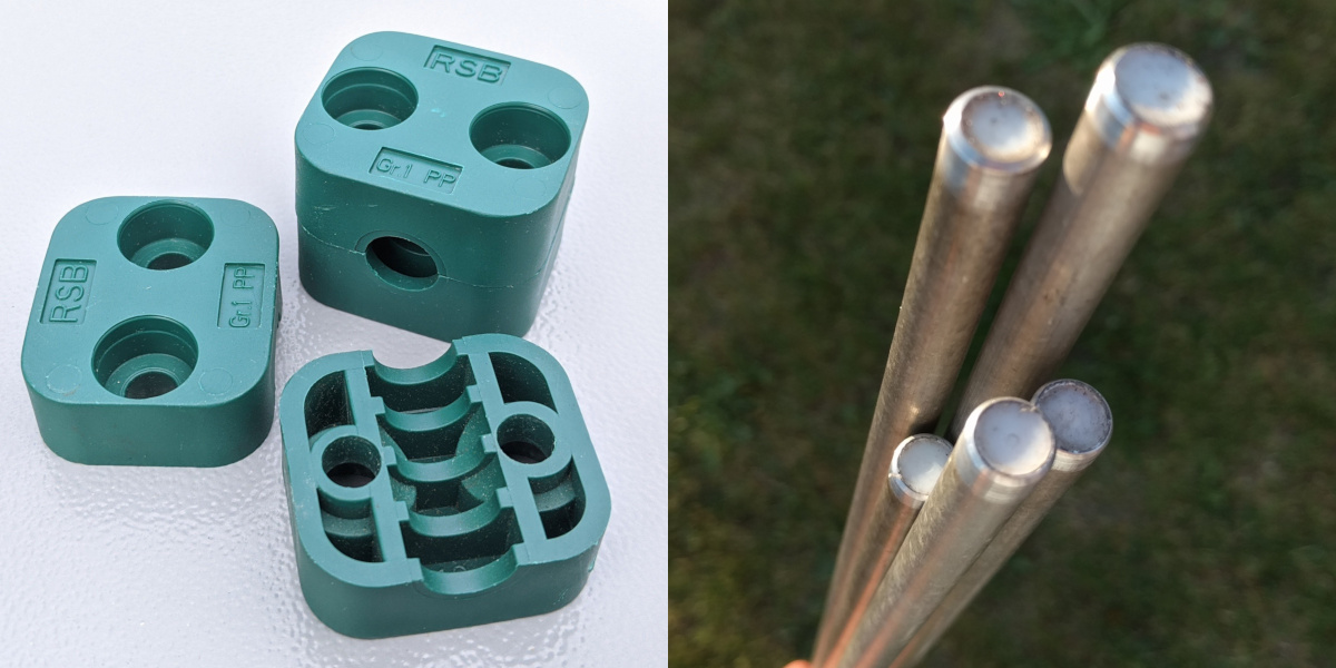
All elements should be installed on insulated mounting brackets. I used RSB RAPR-110 hydraulic tube clamps. Each tube end should be closed. That will prevent acoustic resonance. Furthermore, the water may freeze inside an element and break it in a result during the wintertime. I used some teflon plugs for that.
I think that bending a tubular driven element is the most difficult part of this construction. It is not so easy to bend a dipole that perfectly matches all dimensions. Finally, after some corrections, I managed to obtain a precision of each driven element of around 1 mm.
For each antenna I made a typical half-wave coaxial balun. The cable has a velocity factor of 0.84, so the matching coax segment length is 300 / 98 / 2 × 0.84 = 128.6 cm. Additionally I put a ferrite choke to reject any unwanted shield current. All connections at the feedpoint are joined with a special bi-metallic Cu/Al washers. Always use very short leads at the feed-point, as they can introduce much stray reactance.
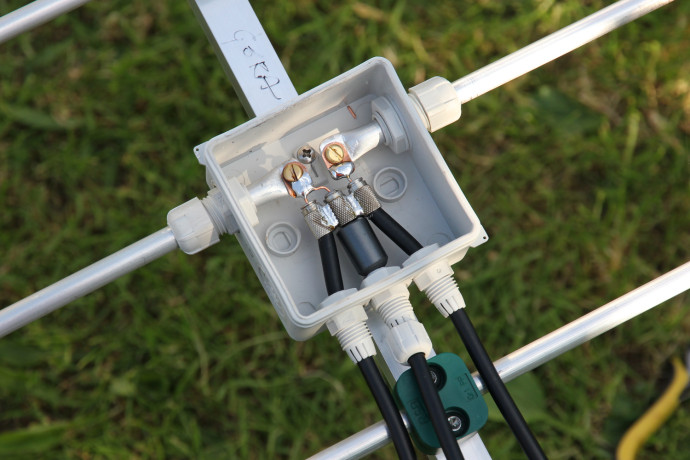
My coax has an aluminium braid, so I put a piece of F-connector on each cable to solder the balun. The cable glands should keep the water away. Additionally I used a spray dedicated for PCB coating to protect all connections.
Stacking
Stacking two Yagis next to each other in a horizontal plane makes the main-lobe significantly narrower. However the mutual interaction between elements in vertical polarization degrades the F/B performance, in the worst case to around 20 dB, as the model suggest. Placing two antennas above each is unfavorable for DX-ing, because the azimuth pattern stays untouched. Stacking in a vertical plane has also another disadvantage – it is mechanically difficult.
Personally, I think that stacking distance 200 cm or a little less is the best for this configuration. The shorter distance, the wider main lobe is and the deeper nulls between main and side-lobes are. The longer distance, the bigger side-lobes are, especially at the top of the band. The changes in gain are negligible. My 2x 9-el setup has currently a stacking distance of 190 cm. The following plots compare the stack with a single antenna.
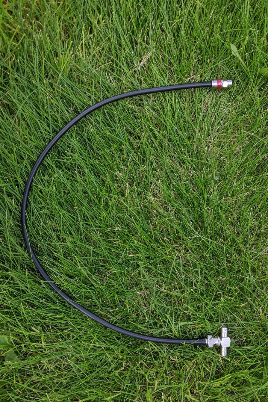
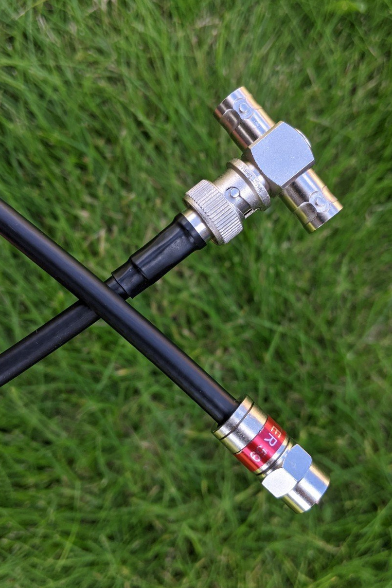
I combined both antennas with a T BNC adapter. The cable length between each antenna and the T adapter must be the same. Combining two 75Ω signals results in a 37.5 Ω output. Matching 37.5 Ω back to 75 Ω is done with a 1/4λ 50 Ω coax. I used Andrew CNT240 cable with 83% velocity ratio with a length of 300/98/4*0.83 = 63.5 cm.
Measurements
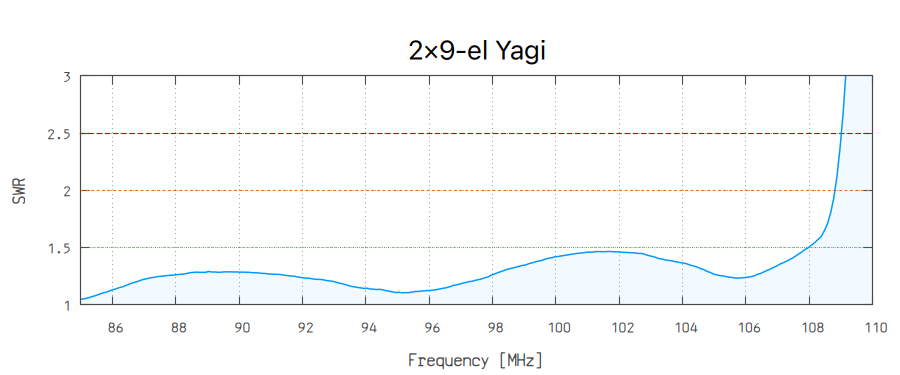
The following SWR measurements of 2×9-el Yagi were done using NanoVNA V2 Plus4:
- Vertical polarization (with 15 m of Triset 113 cable):
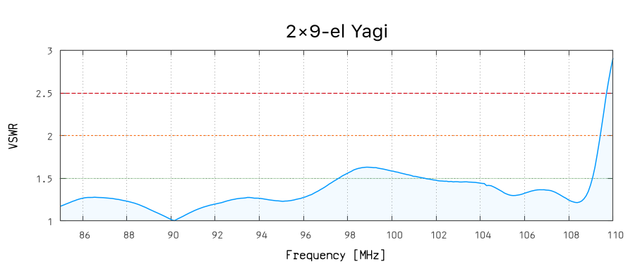
- Horizontal polarization (calibrated directly at the twelfth-wave transformer):
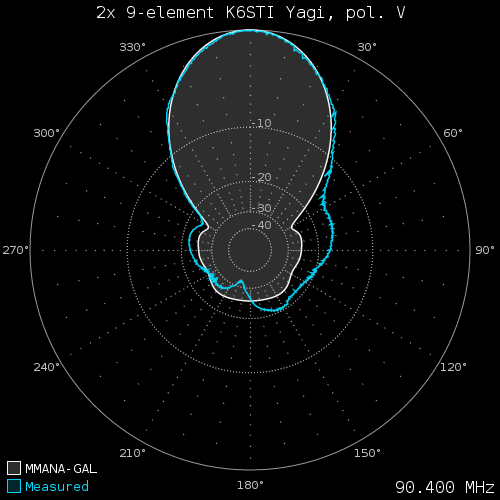
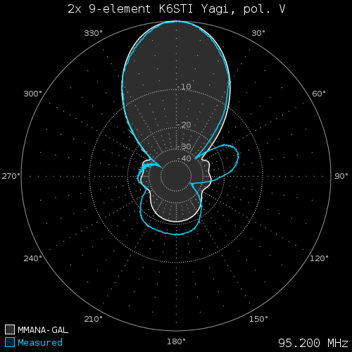
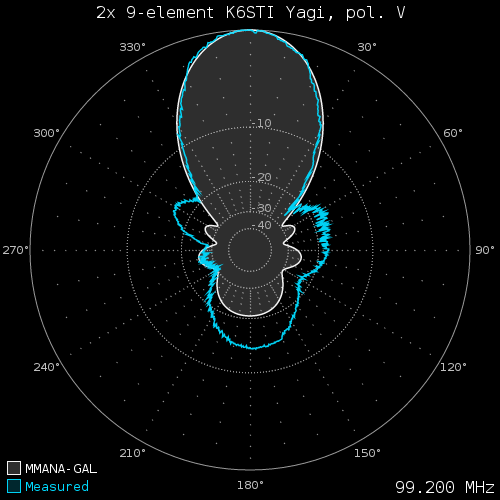
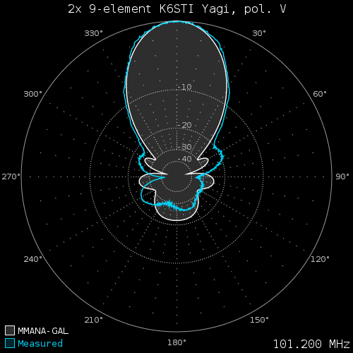
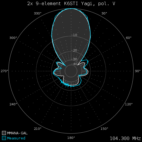
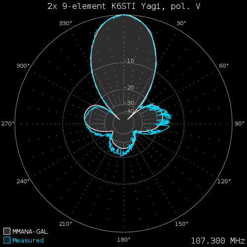
The antenna patterns were measured with a modified Sony XDR-F1HD tuner and XDR-GTK software. The multipath influence is visible as a choppy signal on the following plots. Signal attenuators were required because of a very strong local signals (90.4 86 dBf, 95.2 82 dBf, 101.2 88 dBf, 104.3 104 dBf!) that cause AGC clipping.
- 90.4 MHz: VOX FM Płock, 0.5 kW ERP @ 6 km, with 16 dB attenuator, peak 86 dBf (att. to 56 dBf):
- 95.2 MHz: Eska Płock 0.1 kW ERP @ 6 km, with 26 dB attenuator, peak 82 dBf (att. to 56 dBf):
- 99.2 MHz: PR Łódź, 30 kW ERP @ 95 km, with 16 dB attenuator, peak 62 dBf (att. to 46 dBf):
- 101.2 MHz: TOK FM Płock, 1 kW ERP @ 9 km, with 30 dB attenuator, peak 88 dBf (att. to 58 dBf):
- 104.3 MHz: KRDP Płock, 1 kW ERP @ 5 km, with 46 dB attenuator, peak 104 dBf (att. to 58 dBf):
- 107.3 MHz: PR24 Łodź, 1.5 kW ERP @ 95 km, with 12 dB attenuator, peak 52 dBf (att. to 40 dBf):
Construction flaws
Aluminium tubes 10×1 mm are the weakest part of this construction. Frequent vibrations weaken the material near the element mounts. While it it safe to use thick tubes for the dipole and all directors, the reflectors will eventually break after a year or two. Of course this will likely happen during winter, when they cannot be easily replaced.
The 10×2 mm aluminium tubes were unavailable in my nearby store, so I reinforced all reflectors with a short fiberglass rods (20 cm × 8 mm) at the element centers.
Well… this was still not enough, because the longest reflector broke again in April 2016, but this time at around ¼ of its height. Perhaps it was already damaged when I attached it to the antenna, as I do not see any other possibility. Nevertheless, I replaced the longest reflector in both antennas to an alumiunim rod and so far the problem is finally gone.
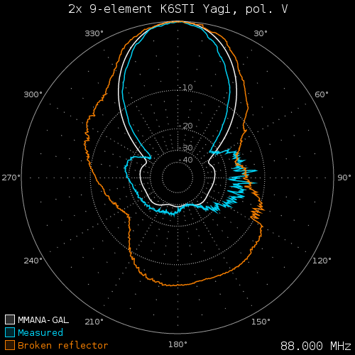
The following plot compares the pattern before and after the replacement. What a difference! The broken reflector actually acted as a director, especially for the bottom of 88-108 MHz band.
Summary
Although the reception is much more propagation dependent than just the antenna, it is worth mentioning about real-world FM-DX results. The following list contains stations which I have received in central Poland via tropospheric ducting propagation in few last years:
- The Netherlands @ 900-1000 km (reports: 11.02.2015, 02.10.2015, 31.10.2015, …),
- The UK @ 1300-1500 km, incl. BBC R4 from Holme Moss @ 1443 km with RDS (read full report),
- Norway: 98.6 Radio Sør from Kristiansand @ 968 km, listed as 0.5 kW ERP (read full report),
- 15 stations from Italy @ 1200+ km and other from BIH, HRV, SVN (read full report),
- …and many, many other stations which are listed in my DX log.
The following video presents the rotation of my initial 2× 9-el setup in July 2013. An extended stacking distance over 220 cm provided a sharp main-lobe with deep nulls, but also awful side-lobes, reaching -10 dB at the top of 88-108 MHz band.