This article describes an extended modification of XDR-S10HDiP.
If you are interested in modifying XDR-F1HD click here
Warning: This write-up is provided as is. Do everything on your own responsibility! There’s always a risk of a permanent damage to your tuner! Always unplug the power cord and use a properly grounded soldering iron during the modification.
Features
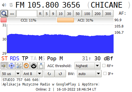
- Tuner control with a computer.
- Wide frequency tuning range (from 60 to 130 MHz).
- Tuning steps: 1 kHz (LW/MW/SW), 5 kHz (VHF).
- Fixed or adaptive digital IF bandwidth.
- Precise signal level meter and squelch function.
- AM or FM demodulation on any frequency.
- RDS fast PI mode and error correction.
- Selectable de-emphasis and AGC threshold.
- Digital alignment of the antenna circuit.
- RF and IF +6dB gain boost.
Warning: The stock controller & display are fully replaced with a Seeeduino board, therefore tuner cannot be used as stand-alone anymore. We recommend to desolder HD Radio chip to reduce temperatures. This type of modification can be also useful for partially broken units with fully operational DSP/IF module. Currently there is no known way to use this tuner with stock controller and XDR-I2C coexistence.
What’s needed?
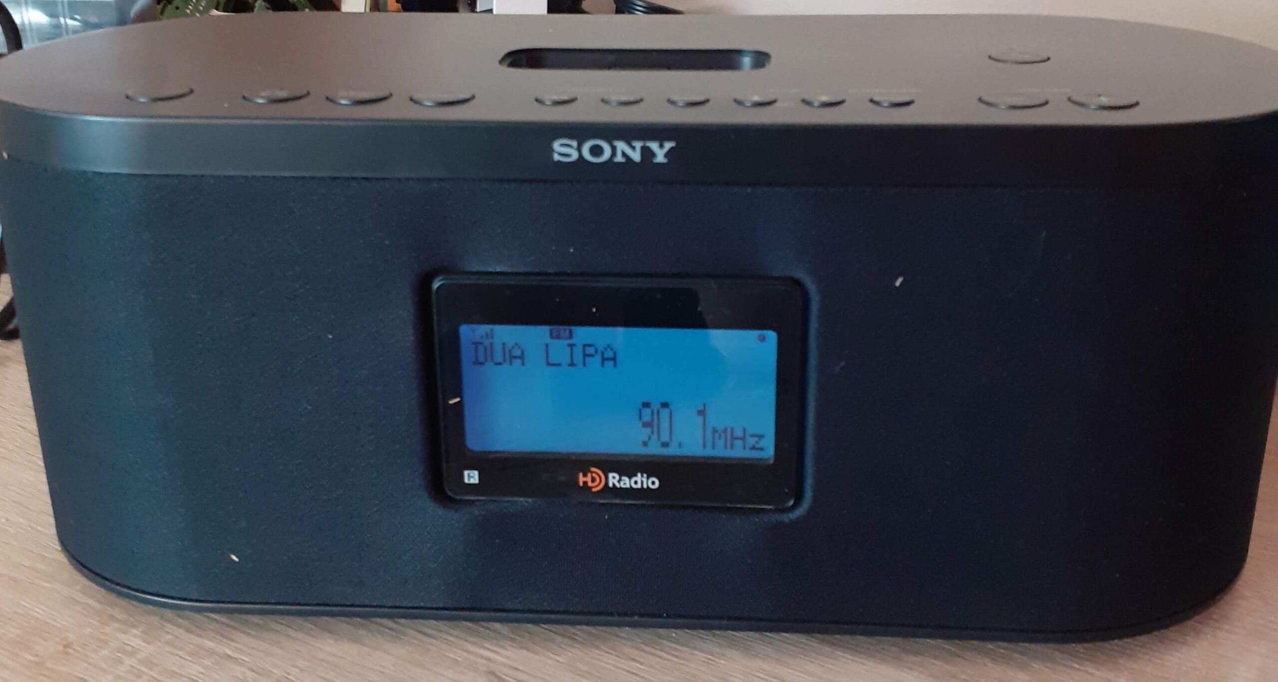
- Sony XDR-S10HDiP tuner.
- Computer with a USB port.
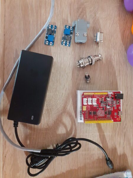
- Seeeduino board (switched to 3.3V operation).
- Micro-USB cable and some wires.
- DC-DC Step-Down Voltage Regulator,DC socket and 12V power supply (if you decide to modify PSU)
- RCA audio socket
- RS-232 cable and socket (if you decide to have Seeeduino board out of the tuner’s case)
Connections (XDR-I2C)
| Seeeduino board |
XDR-S10HDiP | Connector A pin on S10HDiP board |
|
| GND | ↔ | GND | 12 |
| Analog PIN 4 | ↔ | DTUNER_SDA | 10 |
| Analog PIN 5 | ↔ | DTUNER_SCL | 9 |
| Digital PIN 2 | ↔ | DTUNER_RDS | 11 |
| Digital PIN 4 | ↔ | DTUNER_POWER | 2 |
| Digital PIN 5 | ↔ | DTUNER_RESET | 6 |
Software
You can download XDR-I2C software from here
Remember to do this change into xdr-i2c.ino before uploading on Seeeduino board:
#define INIT 0
to
#define INIT 1
Below we post one of modified tuners by UniqueTM with a short description.
We recommend to follow XDR-S10HDiP service manual while modifying the tuner.
Soldering the XDR-I2C modification
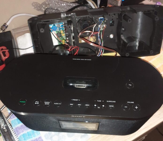
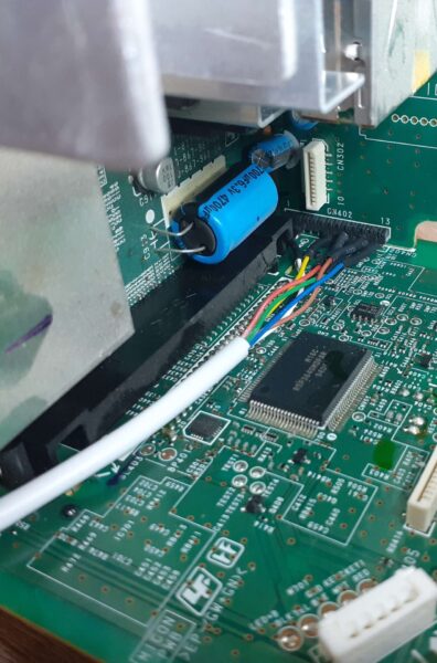
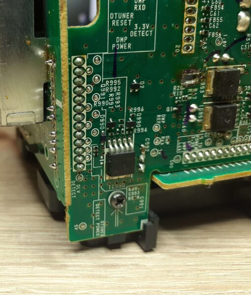
In order for the tuner to run the modification, you need to desolder the display board and connect the Seeeduino wires to pins 2, 6, 9, 10, 11, 12 on connector A (CN402 looking at the tuner schematics)
Solder the display without connecting pins to which the mod is connected. It is best to bend the above pins so that they do not interfere. The remaining ones should be soldered as before. The display will act only as a clock that you can set.
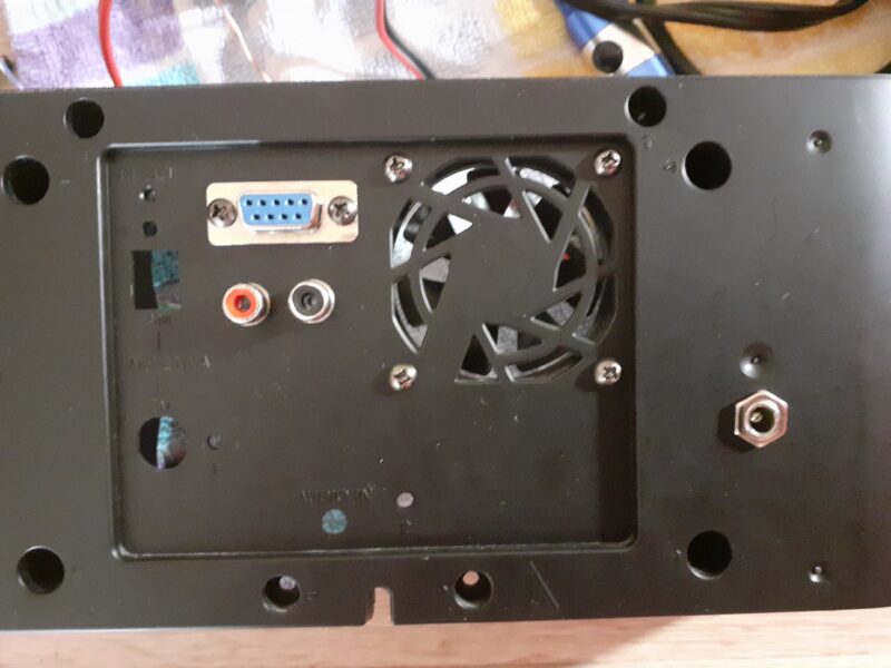
Feeding out L-R audio from the tuner
Also you need to feed out audio. Because speakers won’t work when using modification. You need to output it from the preamplifier, I used pins 2 (R), 4 (L), 7 (GND) at connector B on S10HDiP board.
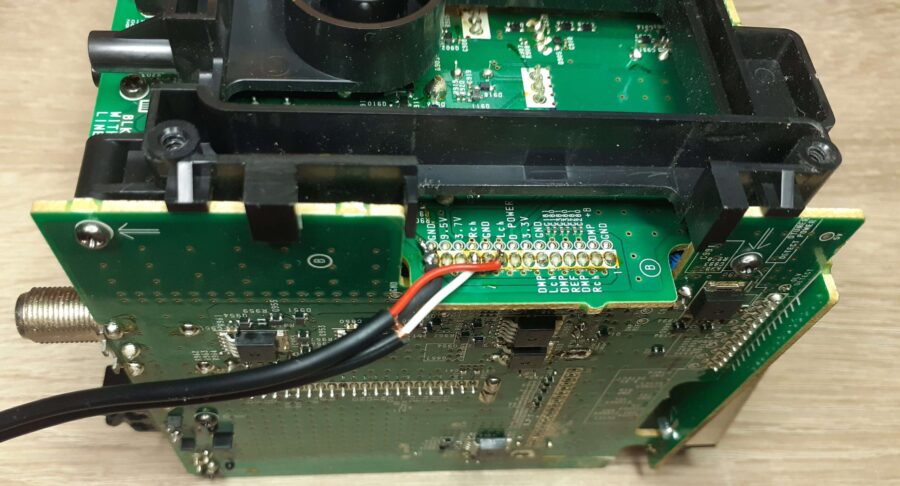
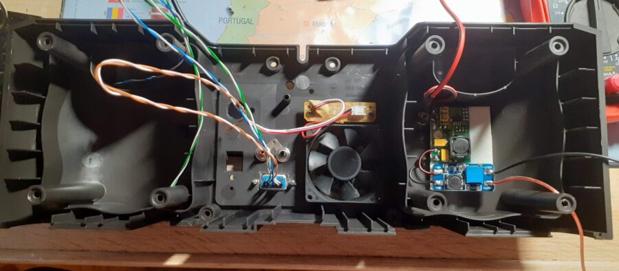
Due to the fact that the tuner does not start with stock controller, the fan will not start. You have to feed him a 5-12V voltage from another place (for example from 7V power supply). It will work all the time but you can use a bimetallic thermostat to make fan’s life longer.
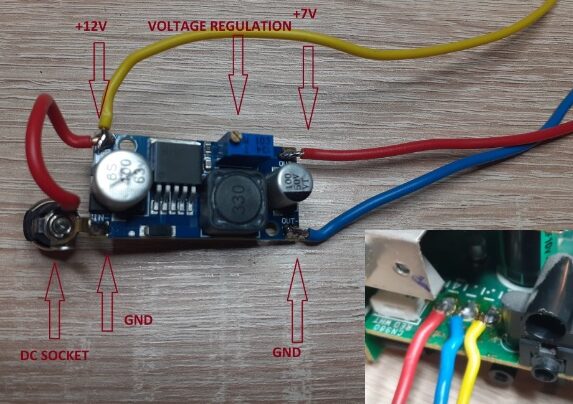
It is not mandatory, but originally PSU uses a frequency of 60 Hz. When connecting the tuner in Europe via a 230 / 110V converter, the tuner works correctly, but the power supply heat up more so it can negatively affect in tuner’s longliveness. The tuner is supplied from the original voltage supply: +12V and +7V. Using a 12V external power supply Yout just need to mount only one step-down converter set to 7V (I mounted it behind one of the speakers, I also mounted a DC socket there), the second voltage (+12V) is given directly.
Tuner will start up automatically.