This article describes an extended modification of XDR-F1HD. The stock controller & display is fully replaced with a Seeeduino board, therefore tuner cannot be used as stand-alone anymore. HD Radio module may be additionally disconnected to keep the internal temperature and power consumption down. This type of modification can be also useful for partially broken units with fully operational DSP/IF module.
Warning: This modification is provided as is. Do everything on your own responsibility! There’s always a risk of a permanent damage to your tuner!! Always unplug the power cord before doing anything inside it and use a properly grounded soldering iron.
Connections:
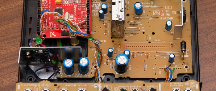
Unlike the standard modification, this variant requires soldering directly to a PCB. Be careful, because the PCB quality is poor and the copper layer may be easily damaged with too much heat.
| Seeeduino | XDR-F1HD | |
| GND | ↔ | GND |
| Analog PIN 4 | ↔ | DTUNER_SDA |
| Analog PIN 5 | ↔ | DTUNER_SCL |
| Digital PIN 2 | ↔ | DTUNER_RDS |
| Digital PIN 4 | ↔ | DTUNER_POWER |
| Digital PIN 5 | ↔ | DTUNER_RESET |
All DTUNER pads are labeled on the bottom of XDR-F1HD’s board. Transistor and IR diode is not used in this modification variant. Tuner will power-up automatically.
Software:
For this modification, a single line in the XDR-I2C source code must be changed from:
#define INIT 0
to:
#define INIT 1
Follow the instructions from XDR-I2C write-up.