XDR-I2C is a modification of the Sony XDR-F1HD radio tuner.
See also a modification of the Sony XDR-S10HDiP tuner here
Warning: This write-up is provided as is. Do everything on your own responsibility! There’s always a risk of a permanent damage to your tuner! Always unplug the power cord and use a properly grounded soldering iron during the modification.
Features
- Tuner control with a computer.
- Wide frequency tuning range (from 60 to 130 MHz).
- Tuning steps: 1 kHz (LW/MW/SW), 5 kHz (VHF).
- Fixed or adaptive digital IF bandwidth.
- Precise signal level meter and squelch function.
- AM or FM demodulation on any frequency.
- RDS fast PI mode and error correction.
- Selectable de-emphasis and AGC threshold.
- Digital alignment of the antenna circuit.
- RF and IF +6dB gain boost.
HD radio is NOT supported!
What’s needed?
- Sony XDR-F1HD tuner.
- Computer with a USB port.
- Seeeduino board (switched to 3.3V operation).
- Mini-USB cable, some wires, resistors and a transistor.
Connections
The following write-up assumes stock controller and Seeeduino co-existence. If you are interested in an extended modification, click here.
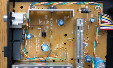
Switch the Seeeduino board to 3.3V mode. GND, SDA, SCL and RDS are connected directly to the Seeeduino board. The RESET line is used to block XDR-F1HD’s stock controller CPU while using this modification and requires a transistor. Do not connect the RESET line directly! Use a typical low power n-mosfet transistor, like BS170. It is connected as a key: source to JW29 (GND), drain to RESET (JW28) and gate to digital pin 4 in Seeeduino.
| Connections | |||
| GND | ↔ | JW29 | |
| Analog PIN 4 | ↔ | JW12 | (I²C SDA) |
| Analog PIN 5 | ↔ | JW13 | (I²C SCL) |
| Digital PIN 2 | ↔ | JW16 | (RDS) |
| Digital PIN 4 | ↔ | BS170 gate | |
| BS170 drain | ↔ | JW28 | (RESET) |
| BS170 source | ↔ | JW29 | (GND) |
| JW25 | ↔ 150 kΩ resistor ↔ | JW21 | |
| optional: | |||
| Digital PIN 3 | ↔ 200 Ω resistor ↔ | IR LED (+) | |
| GND | ↔ | IR LED (-) | |
IR diode can be optionally used for automatic tuner power up. If you don’t connect it, you will have to turn on XDR-F1HD manually every time before starting up the software.
Don’t forget to toggle Seeeduino from 5V to 3.3V operation (mechanical switch on the board). Also consider adding a small fan because XDR-F1HD runs very hot. High temperatures always reduce the lifetime of electronic components.
When the Seeeduino board is unpowered (e.g. a USB cable is disconnected or the computer is powered down), it blocks the I²C bus and tuner will be stuck on a flashing WAIT message. If you want to use modified XDR-F1HD without a computer, connect the internal 10.5V voltage (easily accessible via JW3 jumper) to the Seeeduino’s DC jack pin. Feeding the voltage though DC jack and USB simultaneously results in a thing called USB back-powering. This is a violation of the USB specification and should be avoided. If you want to be 100% safe, disconnect the jack while using USB.
Need an inspiration? Check more pictures of modified tuners.
Source code
Latest version: 2020-02-21 (ZIP). It is compatible with XDR-GTK v1.0 and v1.1.
The development version is hosted on a GitHub repository.
Arduino IDE and drivers
Download the Arduino IDE. Install drivers for the Seeeduino board, which are available in drivers → FTDI USB Drivers directory.
Run the Arduino IDE, choose Tools → Board → Arduino Duemilanove w/ ATMega 328. Open xdr-i2c.ino file and upload it to the Seeeduino board. Mak sure to select correct serial port. Check USB Serial Port device COM number in the Windows Device Manager.
Starting the modification
If you don’t have an IR led, you’ll have to turn on XDR-F1HD manually using the power button. Follow instructions from XDR-GTK page. See the Antenna input alignment paragraph below to fine tune your tuner sensitivity.
Note: When the XDR-I2C is running, XDR-F1HD’s display is dimmed.
Commands
All commands consist of one letter, data and are ended with end-line ASCII character.
- x – start the controller
- T – tune to a frequency [kHz]
T87500 – tune at 87.500 MHz
The controller will return a frequency, possibly rounded depending on the available tuning step. - F – IF digital filter bandwidth (0-15 FM, 16-30 AM, negative number – adaptive bandwidth)
- F0 – set the narrowest FM filter bandwidth (55 kHz)
F15 – set the widest FM filter bandwidth (309 kHz)
F-1 – set adaptive bandwidth - A – AGC threshold level
A0 – highest
A1 – high
A2 – medium
A3 – low - D – de-emphasis mode
D0 – 50 µs
D1 – 75 µs
D2 – off - M – demodulation mode
M0 – FM
M1 – AM - G – RF/IF gain boost
G00 – RF and IF normal gain
G10 – RF +6 dB gain
G01 – IF +6 dB gain
G11 – RF and IF +6 dB gain - V – antenna circuit tuning voltage
V0 – set minimal voltage
…
V127 – set maximal voltage - S – spectral scan, reads signal levels from a desired frequency range (experimental!)
Sa87500 – set start frequency [kHz]
Sb108000 – set end frequency [kHz]
Sc100 – set step [kHz]
Sf3 – set filter
Sz – set antenna
S – perform the spectral scan
Sm – like above, but multiple times (continuous) - Y – audio volume
Y0 – mute
…
Y100 – set highest volume - Q – squelch threshold level
Q0 – squelch off
Q10 – squelch at 10 dBf
Q-1 – stereo squelch - Z – antenna switch
Z0 – set high state on digital pin 8
Z1 – set high state on digital pin 9
Z2 – set high state on digital pin 10
Z3 – set high state on digital pin 11 - C – antenna rotator
C0 – set low state on digital pin 6 (CW) and 7 (CCW)
C1 – set high state only on digital pin 6 (CW)
C2 – set high state only on digital pin 7 (CCW) - X – shutdown the tuner
Antenna input alignment
Each tuner requires an individual alignment of the antenna circuit. XDR-I2C source code contains values optimal for my unit, which will reduce the sensitivity of your tuner. You can align the tuner using:
- a signal generator,
- FM stations with stable signal levels.
The user interface XDR-GTK has an antenna input alignment slider, which can be enabled in settings (Antenna tab). Find out a value that provides the best signal level for a given frequency. Use an antenna attenuator for a very strong signals (70-80 dBf or more), as they may be clipped with the tuner AGC.
Write down optimal values, change them in the source code (align.ino file, you can modify or add more frequency ranges) and re-upload XDR-I2C to the Seeeduino board with the Arduino IDE. Keep your modified file for future firmware updates!